Flash Trigger External Antennae Mod.

BobSaget

TPF Noob!
Joined
Nov 15, 2012
Messages
151
Reaction score
29
Location
New Olreans
Can others edit my Photos
Photos OK to edit
It's been a while since I posted on this forum, but thought I'd share this recent modification i made to a Promaster flash trigger. I noticed i wasn't getting much distance out of the thing and decided to take a look at the circuit board and see what kind of antennae was inside.

1 $IMGP3367.jpg
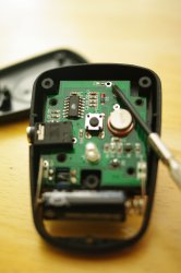
As you can see, there was no antenna to be found but there was a port on the board for one (I have my screwdriver pointed at it.) I tested this by getting out of range and then connecting a wire to the port to see if i could get it to fire and was successful. I ran over to a thrift store and found a 2 dollar cordless phone with a nice stubby rubber antenna.

2$IMGP3390.jpg

Next, had to do a little drilling and soldering and here's my end result.

3$IMGP3409.jpg
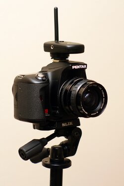
Added bonus, while i was at the thrift store i found a Slik Tripod head for 7 bucks. (in pic 3)
 
You left out one part.


Does it work,and what kind of range did you get out of it??
 
Yes, but i'm not sure how much its range has improved yet. I'll update after I bring it out for a run.
 
No, the trigger is 2.4GHz and the phone was 900mhz. Regardless, I only used the antenna out of the phone, basically a metal rod. The phone was chosen for its antenna size and rubber enclosure.
 
Yes, but AE length is all important; you may find little to no range increase simply because of the wave-length mis-match causes the AE to generate a [relatively] large SWR. That said, 900 goes into 2400 close enough to 3x that it should work decently I would think. I'd be very interested in seeing what your range increase is with this.
 
Thanks for the info. This wasn't the most scientific endeavor :wink:. Basically, when i noticed i was getting a result when going back and forth, ae on, ae off, I figured it would be worth it. Sometimes my interest in taking things apart and screwing with them outweighs the practicality but i think i may get a good result with this one.
 
Cool - I'd really like to seem some data on this, especially because it's such a simple mod.
 
Ideally the length of the antenna should be 5/8 of a wavelength. However, that does not necessarily make for a good impedance match. Given that we don't know what the output impedance of the device is, and the fact that there is essentially a zero length transmission line, it might make little real difference.

The essence is that any length from 1/4 wavelength to 5/8 wavelength is going to be fairly similar. At 2400 mHz 5/8 wavelength is about 2.9 inches. Hence almost any length from 1 inch to 3 inches will work well enough. And short of actually measuring the signal you'll be hard pressed to see any difference.

Technically, note that for lengths longer than 5/8 wavelength there is additional antenna gain, but it comes at a cost! The cost is more directivity, and that directivity is towards the axis of the antenna rather than perpendicular. Hence a 1 wavelength antenna will send a significant amount of signal towards the ceiling instead of towards a receiver. That is why you don't want an antenna longer than 3". And the impedance of a 5/8 wavelength end fed antenna is fairly high, while a 1/4 wavelength end fed antenna is fairly low. The device probably has a relatively low impedance. So it is very likely that an antenna shorter than 2.9 inches is a better idea. People talk about something called "SWR", but what it really means is if the output impedance of the device is the same as the input impedance of the antenna more power will be produced. An unmatched 5/8 wavelength antenna might have more gain, but the output device will produce less power compared to use with a 1/4 wavelength.

I think I'd trim the length to about 1.2 inches from the point it connects to the circuit board.
 
Last edited:
It's triggering consistently at a range of 80' to 85.' Past 50' the antenna needs to be pointed upward or no trigger. I wish I would have performed a distance test before hand. Mr. Wizard would be pissed.
 
Ideally the length of the antenna should be 5/8 of a wavelength. However, that does not necessarily make for a good impedance match. Given that we don't know what the output impedance of the device is, and the fact that there is essentially a zero length transmission line, it might make little real difference.

The essence is that any length from 1/4 wavelength to 5/8 wavelength is going to be fairly similar. At 2400 mHz 5/8 wavelength is about 2.9 inches. Hence almost any length from 1 inch to 3 inches will work well enough. And short of actually measuring the signal you'll be hard pressed to see any difference.

Technically, note that for lengths longer than 5/8 wavelength there is additional antenna gain, but it comes at a cost! The cost is more directivity, and that directivity is towards the axis of the antenna rather than perpendicular. Hence a 1 wavelength antenna will send a significant amount of signal towards the ceiling instead of towards a receiver. That is why you don't want an antenna longer than 3". And the impedance of a 5/8 wavelength end fed antenna is fairly high, while a 1/4 wavelength end fed antenna is fairly low. The device probably has a relatively low impedance. So it is very likely that an antenna shorter than 2.9 inches is a better idea. People talk about something called "SWR", but what it really means is if the output impedance of the device is the same as the input impedance of the antenna more power will be produced. An unmatched 5/8 wavelength antenna might have more gain, but the output device will produce less power compared to use with a 1/4 wavelength.

I think I'd trim the length to about 1.2 inches from the point it connects to the circuit board.


Daaayyum.
Maybe he shoulda just left that piece of wire jammed in there.
 

Most reactions

New Topics

Back
Top